Integer factorization: 77 = 7 × 11
Factorization is the first problem the chip solved that genuinely needs annealing: the ferro4 and af4 examples are solved by a plain quench, this one needs a hot noise source. Below is one complete example from mathematics to currents to the answer, plus a scalability analysis.
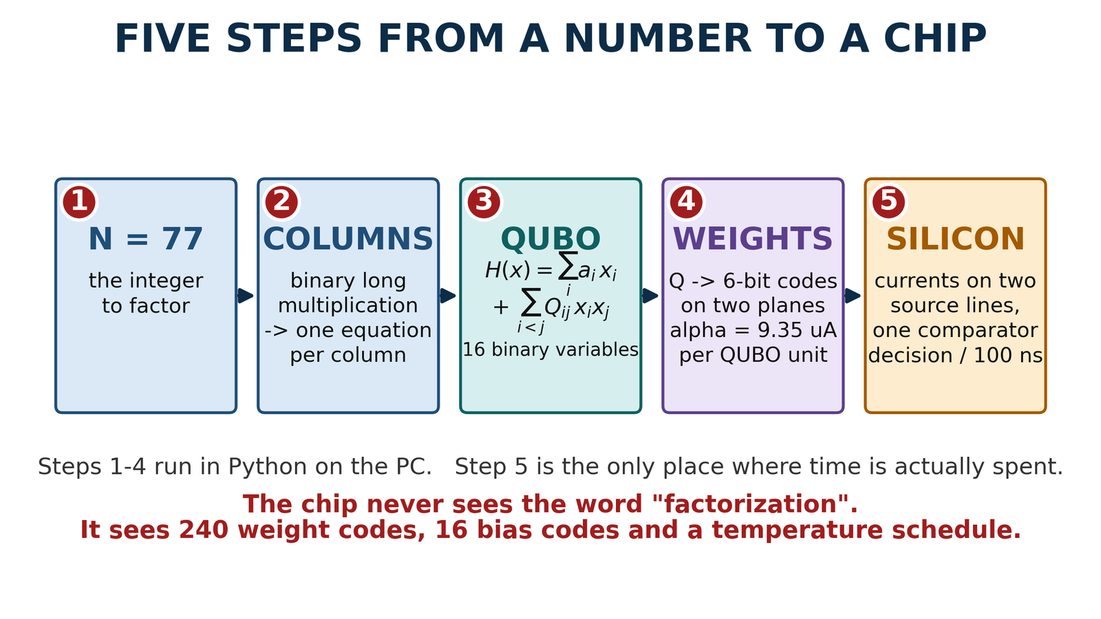
| Mathematics | Physics on the chip | In this example |
|---|---|---|
| binary variable xj | word line WLj = 0 V / 1.0 V | 16 of 16 word lines used |
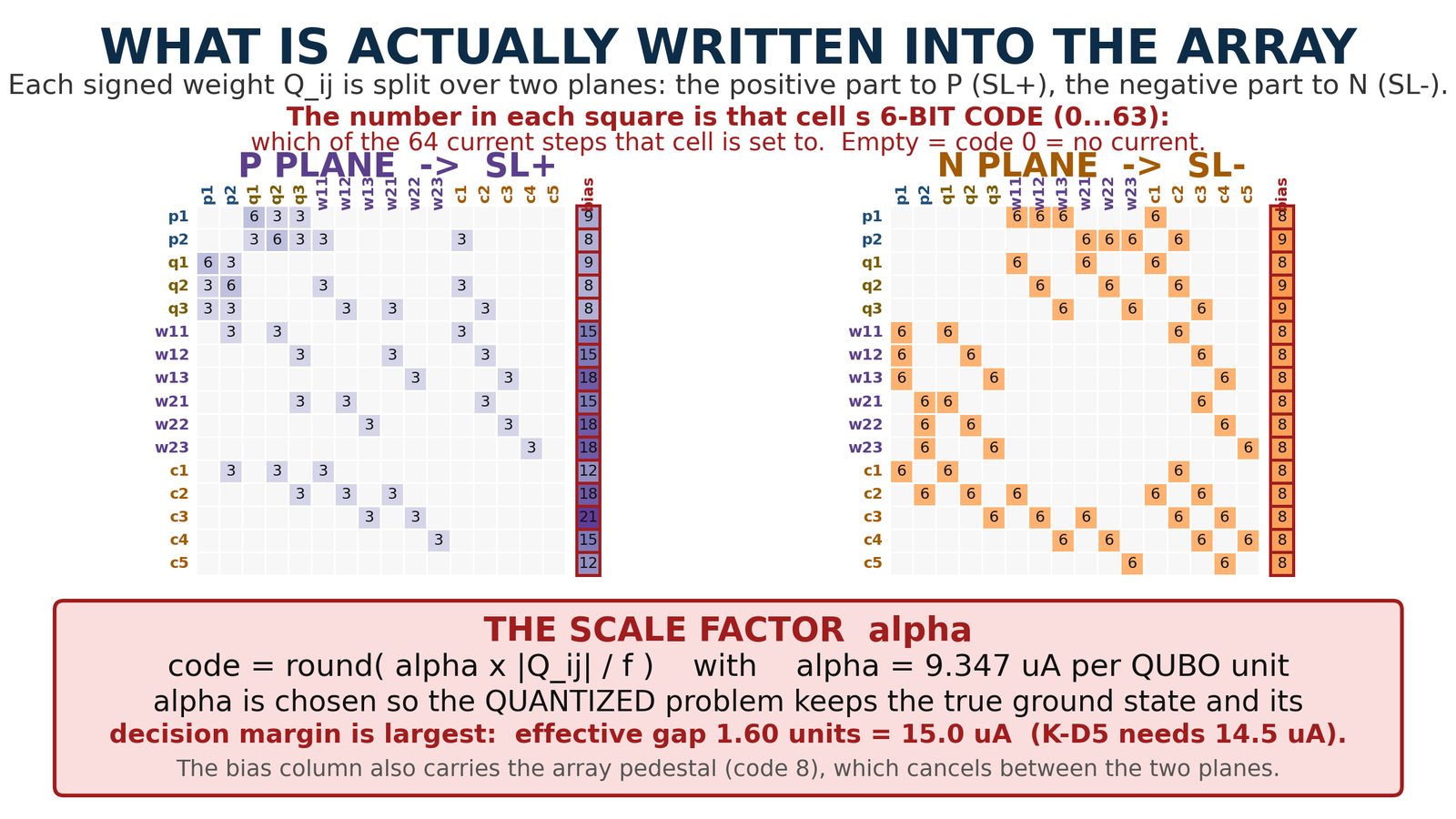
| coupling Qij | 6-bit code → synapse current DAC | α = 9.347 µA per QUBO unit |
| bias ai | always-on bias cell, column 17 | code-8 pedestal + ai |
| local field ∂H/∂xi | source-line difference I(SL+) − I(SL−) | worst row 351 µA of the 400 µA budget |
| sign(∂H/∂xi) | StrongARM comparator, BSENSE vs BREF | one decision per 100 ns slot |
| energy gap of the quantized problem | the decision margin the comparator sees | 1.60 units = 15.0 µA (14.5 needed) |
| temperature T | differential amplitude of the noise source | 0 … 91 µA (NCODE 0 … 63) |
| annealing schedule | SCHED table (code, dwell) + quench | 76 supercycles = 121.6 µs |
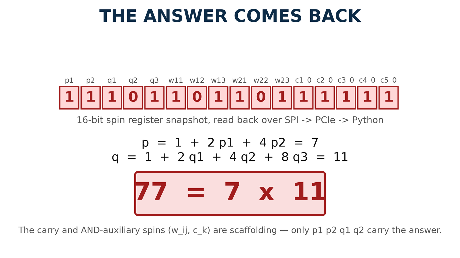
| ground state argmin H | content of the 16-bit spin register | 1110110110111111 |
| the answer | read back: SPI → PCIe → Python | 77 = 7 × 11 |
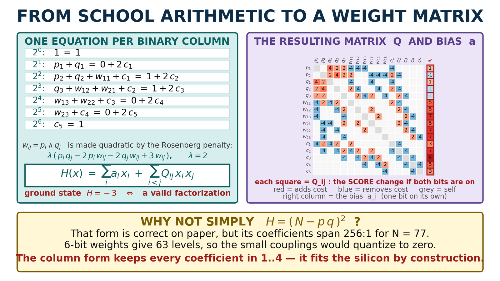
The formulation is a hardware decision
H = (N − pq)² is correct on paper, but its coefficients span a 256:1 range; with 6-bit weights the small couplings quantize to zero. The column form of schoolbook arithmetic (one equation per binary column plus carry bits, reduced to quadratic with the Rosenberg penalty) keeps every coefficient within 1…4 and fits the silicon by construction.
α is valid only in discrete bands
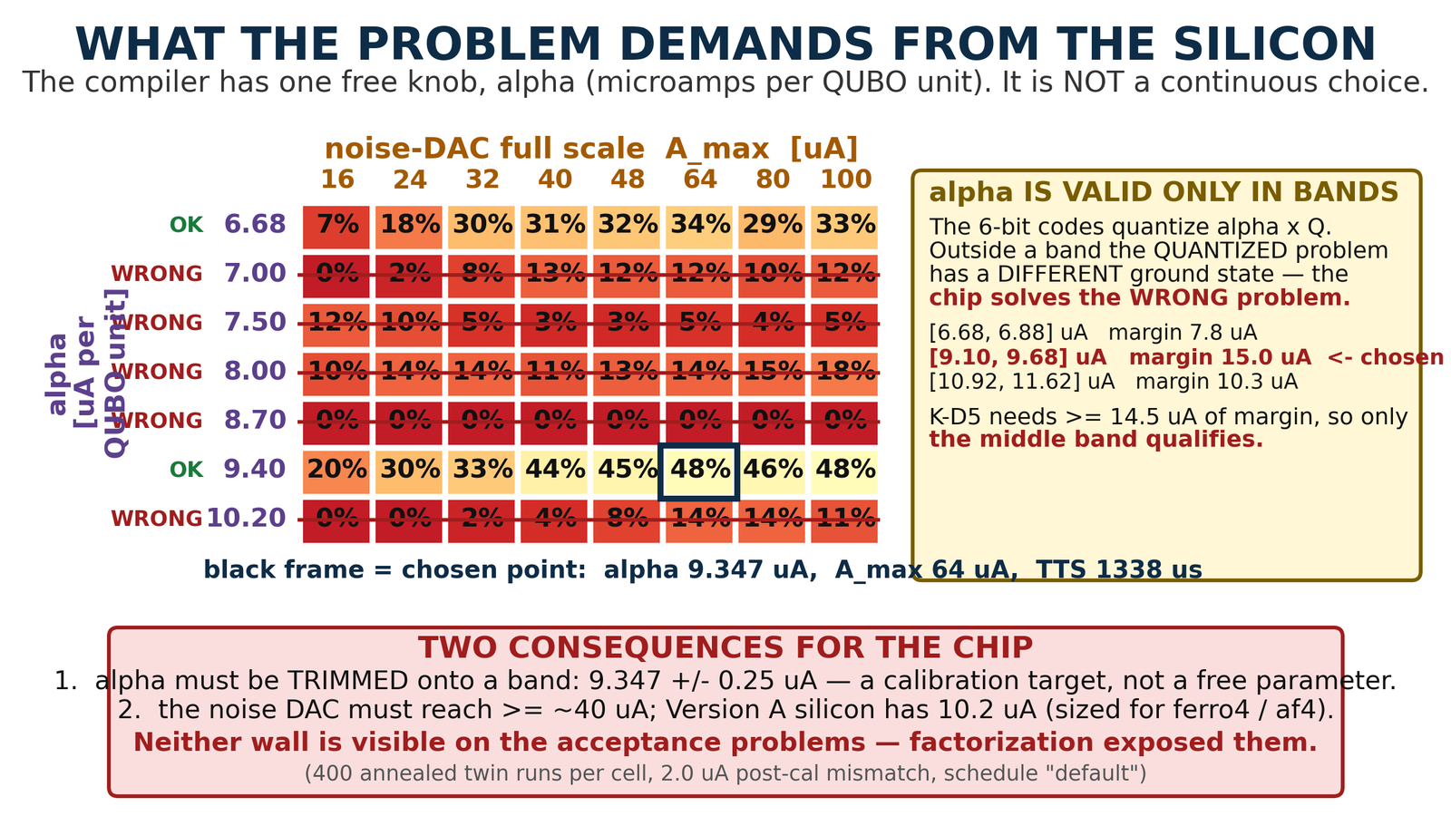
The compiler's single free knob is α (microamps per QUBO unit). Because of the 6-bit quantization, if α leaves a band the codes change the ground state: the chip then holds a different problem.
- Valid bands for N = 77: [6.68, 6.88], [9.10, 9.68], [10.92, 11.62] µA. Only the middle band clears the K-D5 decision margin (14.5 µA).
- Chosen α = 9.347 ± 0.25 µA: a trim target, not a free parameter.
- Noise amplitude: at Amax ≈ 40 µA and above, 44–48 % success per anneal; with too little noise, 20 %.
Both results (the α band rule and the ≥ 40 µA noise requirement) were carried into the compiler contract and the specification of the next revision.
The run and the answer
| Verification level | Result |
|---|---|
| Exhaustive enumeration of all 216 states | Both the ideal and the quantized QUBO have 7 × 11 as their ground state (H = −3) |
| Quantized digital twin (measured f(code), row-current droop, post-calibration mismatch) | 48 % of 400 annealed runs land on 77 = 7 × 11; time to solution 1338 µs (> 99.9 % with 11 restarts) |
| Transistor level, full tile, closed loop | A 4-supercycle N = 35 deck reached the correct ground state (7 × 5); the 76-supercycle N = 77 deck is generated |
| Not yet done | BREF re-calibration for this problem; corner / Monte-Carlo analysis of the factorization tile |
How many digits with an eFlash-based ASIC?
Two-digit N was solved. If the weight cell were 16-bit eFlash, where does the limit move? The answer was measured with the compiler itself (generating column-form QUBOs for 3 … 165-bit factors), not estimated.
| Digits | N bits | Spins | Weight bits needed | Worst row current (α = 9.35 µA) |
|---|---|---|---|---|
| 2 (N = 77) | 7 | 15 | 6 | 0.9 mA |
| 3 | 8–9 | 20–32 | 7 | 1.0–2.4 mA |
| 5 | 16 | 84 | 8 | 5.9 mA |
| 10 | 32 | 318 | 9 | 26 mA |
| 20 | 64 | 1 194 | 11 | 111 mA |
| 100 (RSA-100) | 330 | 28 765 | 15 | 2.6 A |
1 · Precision: not the limit
The dynamic range of the column-form QUBO grows very slowly: 15 bits even at 100 digits. A 16-bit cell is enough.
2 · Row current: the real hardware wall
Every spin row sums its couplings by Kirchhoff. 1 mA at 3 digits (Version A budget 400 µA), 5.9 mA at 5 digits, 26 mA at 10. Lowering α is no escape: below ≈ 5 µA the decision drowns in noise. With a few-mA conveyor, 4–6 digits.
3 · Spin count
84 rows at 5 digits, 318 at 10, 1 194 at 20. A single dense tile with 256–1024 rows has room for 9–20 digits, but the row-current wall comes first.
4 · Annealing difficulty
48 % success per anneal at 16 spins; it falls exponentially with the spin count. The annealer-based factorization literature tops out around 18–20 bits (6 digits).
Conclusion: what eFlash buys is density and persistence (one cell instead of 18 transistors + 12 latch bits; the weight survives power-off), not current. The row current is an architectural wall: either the read-out floor is lowered or the row is split into tiles; each buys only one or two orders of magnitude. The realistic target is 4–6 digits; with a tiled architecture and a lower read-out floor, 8–10. RSA-class sizes are out of reach in this architecture.